Fundamentals of Thermal Resistance

The Thermal Resistance Analogy

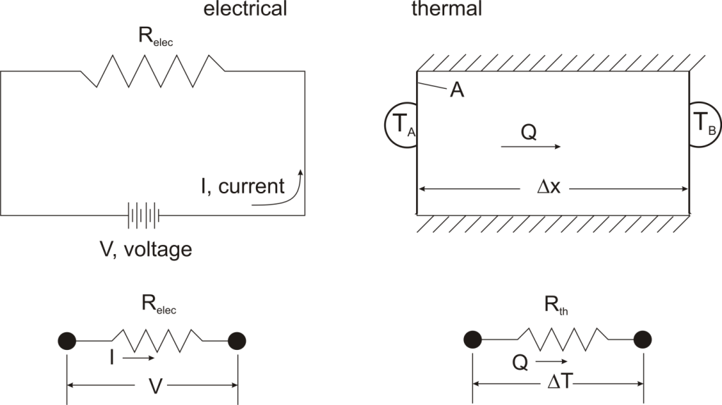
Thermal resistance is a convenient way of analyzing some heat transfer problems using an electrical analogy in order to make complicated systems easier to visualize and analyze. It is based on an analogy with Ohm’s law which is:

Ohms Law

In Ohm’s law for electricity, “V” is the voltage which drives a current of magnitude “I”. The amount of current that flows for a given voltage is proportional to the resistance (Relec). For an electrical conductor, the resistance depends on the material properties (copper tends to have a lower resistance than wood, for example) and the physical configuration (thick short wires have less resistance than long thin wires).
pic2


For one-dimensional, steady-state heat transfer problems with no internal heat generation, the heat flow is proportional to a temperature difference according to this equation:

pic3

where Q is the heat flow, k is the material property of thermal conductivity, A is the area normal to the flow of heat, Δx is the distance that the heat flows, and ΔT is the temperature difference driving the heat flow.

If we create an analogy by saying that electrical current flows like heat, and saying that voltage drives the electrical current like the temperature difference drives the heat flow, we can write the heat flow equation in a form similar to Ohm’s law: pic4where Rth is the thermal resistance defined as: pic5Just as with the electrical resistance, the thermal resistance will be higher for a small cross-sectional area of heat flow (A) or for a long distance (Δx).

Rationale

Now, why bother with all that? The answer is that thermal resistance allows us to solve somewhat complicated problems in relatively simple ways. We’ll talk more about different ways in which it can be used, but first let’s look at a simple case in order to illustrate the benefit.

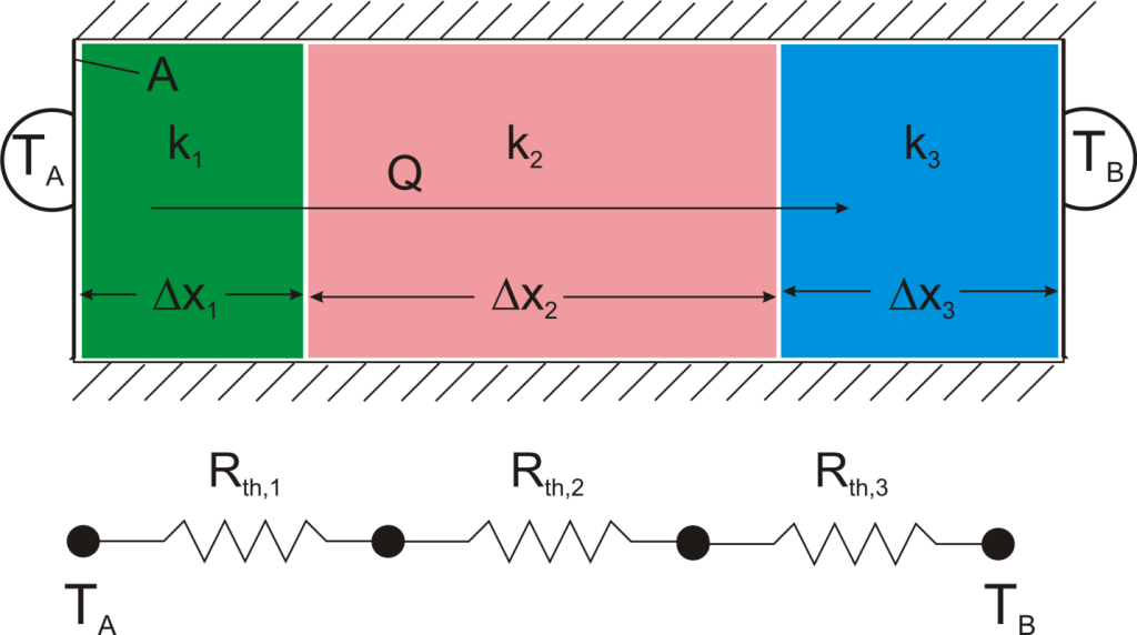
Suppose that we want to calculate the heat flow through a wall composed of three different materials, and we know the surface temperatures at each outside surface, TA, and TB, and the material properties and geometries.
pic6


We could write the conduction equation for each material:

pic7

Now, we have three equations, and three unknowns: T1, T2, and Q. For this case it wouldn’t be too much work to algebraically solve for those three unknowns, however, if we use the thermal resistance analogy, we don’t even have to do that much work:

pic8

wherepic9

and we can solve for Q in a single step.

Combining Thermal Resistances

This simple example showed how to combine multiple thermal resistances in series which is the same structure as in the electrical analog:

pic10

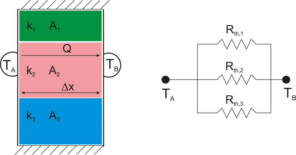
Just like electrical resistances, thermal resistances can also be combined in parallel, or in both series and parallel:

pic11

pic12

pic13

Beyond Conduction

So far, we’ve talked about the thermal resistance associated with conduction through a plane wall. For steady-state, one-dimensional problems, other heat transfer equations can be formulated into a thermal resistance format. For example, examine Newton’s Law of Cooling for convection heat transfer:

pic15

where Q is the heat flow, h is the convective heat transfer coefficient, A is the area over which heat transfer occurs, Ts is the surface temperature on which the convection is taking place, and Tinf is the free-stream temperature of the fluid. As with conduction, there is a temperature difference driving a heat flow. For this case, the thermal resistance would be:

pic16

Similarly, for radiative heat transfer from a gray body:

pic17

where Q is the heat flow, ε is the emissivity of the surface, σ is the Stefan-Boltzmann constant, Ts is the surface temperature of the emitting surface, and Tsurr is the temperature of the surroundings. By factoring the expression for temperature, the thermal resistance can be written: pic18

Advantage: Easy Problem Setup

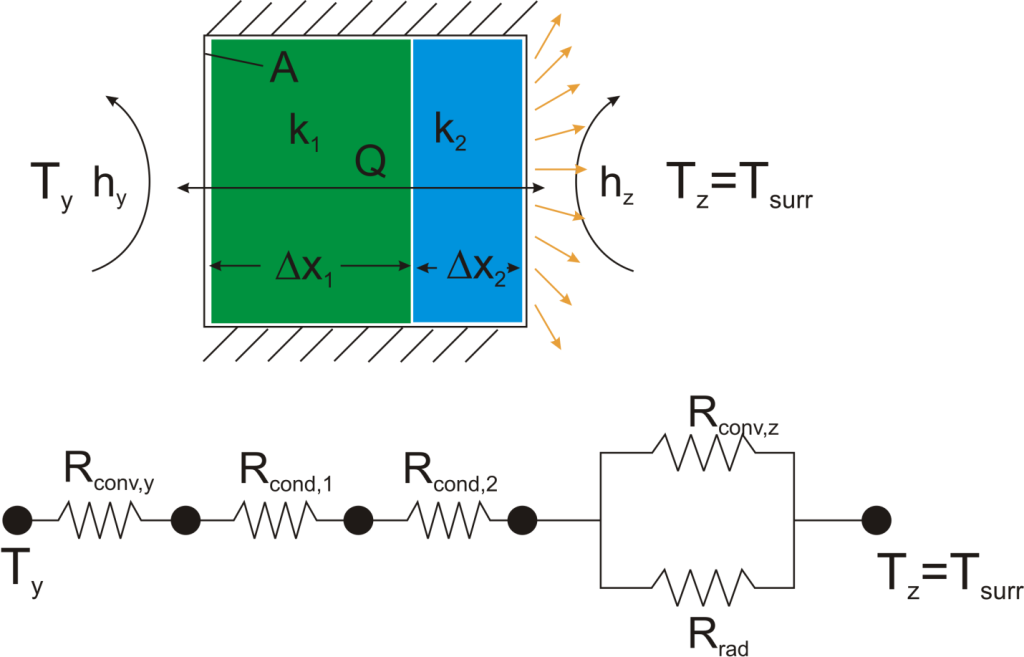
Thermal resistance formulations can make the arrangement of a quite complex problem quite simple to set up. Imagine, for example, that we are trying to calculate the heat flow from a liquid stream of a known temperature through a composite wall to an air stream with convection and radiation occurring on the air side. If the material properties, heat transfer coefficients, and geometry are known, the equation set-up is obvious:

pic19


pic20


Now, to solve this particular problem might involve an iterative solution since the radiative thermal resistance contains the surface temperature inside of it, but the setup is simple and straightforward.

Advantage: Problem Insight
The thermal resistance formulation has the additional advantage of making it very clear which parts of the model are controlling the heat transfer, and which parts are unimportant, or perhaps even negligible. As a concrete illustration, let’s suppose that in the last example the thermal resistance on the liquid side was 20 K/W, that the first layer in the composite wall was 1 mm thick plastic with a thermal resistance of 40 K/W, that the second layer consisted of 2 mm thick steel with a thermal resistance of 0.5 K/W, and that the thermal resistance for convection to the air was 200 K/W, and the thermal resistance to radiation to the surroundings was 2500 K/W coming from a surface with emissivity of 0.5.

pic21


We can understand a lot about the problem by just considering the thermal resistance. For example, since the radiation resistance is in parallel with a much smaller convection resistance, it is going to have a small effect on the overall thermal resistance. Increasing the emissivity of the wall clear to unity would only improve the total thermal resistance by 5%. Or, ignoring radiation completely would cause an error of only 6%. Similarly, the thermal resistance of the steel is in series, and is tiny compared with the other resistances in the system, so no matter what is done to the metal layer it isn’t going to have much effect. Changing from steel to pure copper, for example, would only improve the overall thermal resistance by 0.2%. Finally, it is clear that the controlling thermal resistance is convection on the air side. If it were possible to double the convection coefficient (by, say, increasing the velocity of the air) that step alone would decrease the overall thermal resistance by 36%.

Beyond Plane Wall Conduction

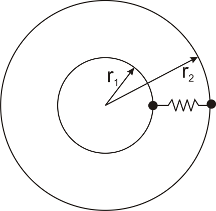
Thermal resistance can also be used for other conduction geometries as long as they can be analyzed as one-dimensional. The thermal resistance to conduction in a cylindrical geometry is:

pic22

where L is the axial distance along the cylinder, and r1 and r2 are as shown in the figure.

Thermal resistance for a spherical geometry is:

pic23

with r1 and r2 as shown in the figure.
pic24
Conclusion

Thermal resistance is a powerful and useful tool for analyzing problems that can be approximated as 1-dimensional, steady-state, and that do not have any sources of heat generation.

MesoGlue Replacing Hot Solder Could Improve Every Device With Circuit Boards

A team led by Prof. Hanchen Huang of Northeastern University has discovered a new way to merge metals at room temperature, without heat by developing a new material called ‘MesoGlue’. Soldering techniques have improved a lot and in large scale circuit board production, most parts of it have been automated. But one thing has remained unchanged throughout the evolution of circuit boards; the hot solder. There has never been another way to attach electronic components to a PCB without melting iron. Not until now.

mesoglue-heatsink-demo.

MesoGlue is a combination of metal and glue. The creators have used metallic nanorods with cores coated with elements Indium and Galium on either side of the two surfaces that need to be joined. When the two surfaces come in contact, the nanorods are interlocked, and form a liquid which is solidified by the core of the rods. The resulting bond acts like both, a conductor and a glue. The technology has been patented through Northeastern University.

The bond formed by the MesoGlue is matchless as it provides thermal and electrical conductivity like metal bonds, resistant to high temperature and air leaks. The applications are as wide as attaching miniature components to circuit boards, and attaching metal pipes without welding.

mesoglue-metallic-glue-replaces-solder.

Small circuit components like processors, capacitors and resistors tend to lose their intended potential when heated to attach them to the circuit board. That is why soldering should be done very quickly, and with the smallest drop of iron as possible. This MesoGlue allows fusion of metals without having to heat them.

Though in its early stages, a company founded by Prof. Hanchen, Paul Elliot and Prof. Stephen Stagon has begun mass-producing this glue for commercial applications. By eliminating the need for heat, this metallic glue could improve the performance of every device that has circuit boards in them.

Researchers developing new thermal interface materials

In the microelectronics world, the military and private sectors alike need solutions to technological challenges. Dr. Mustafa Akbulut, assistant professor of chemical engineering, and two students lead a project funded by DARPA to create thermal interface materials (TIMs) that have a superior ability to transfer heat and a strong capacity to keep cool.

In evaluating a central processing unit, as an example, there are many pieces that individually need temperature management. “As you get smaller and smaller, there is higher heat dissipation per unit area. Locally, you have higher temperatures…you have a harder time operationally—you need better thermal interface materials. This is especially important for radars, laser systems and also for military electronics,” said Akbulut.
Essentially and most critically, the device needs the ability to avoid overheating. As Akbulut asserts, “unless you cool it, it fails.”
In evaluating an electronic device and a cooling system that need to be placed together as they function, if there is an absence of thermal material in between, the heat created by the electronic device can potentially erode the device. According to Akbulut, non-soft materials are considered less effective as a TIM because they do not adequately cover all interior openings or gaps, even though the naked eye may not detect this space.
Akbulut explains why optimal contact is not achieved through current technology. “If you look at the very fine scale, [these two pieces] are not smooth. If you look at these with an electron microscope, you see they are like mountains. If you bring these surfaces together, they do not have perfect contact.” Thus, the objective of a traditional TIM is not fully met.
Soft materials, including paste, often minimize the gap, said Akbulut. The invention of his new metal-based, soft material leads to high thermal conductive activity and because of its malleable nature, consistent contact is achieved. His research group has recently developed TIMs with thermal conductivity greater than 100 W/m-k and elastic modulus values in the order of 20 GPa, significantly advancing the current state of art for TIMs. As a comparison, this material is ten times softer than steel and three times more thermally conductive.
Using copper and nano-materials together, Akbulut believes his new TIM can lead to greater optimization and large-scale implementation in the future.

Nusselt Number

In heat transfer at a boundary (surface) within a fluid, the Nusselt number (Nu) is the ratio of convective to conductive heat transfer across (normal to) the boundary. In this context, convection includes both advection and diffusion. Named after Wilhelm Nusselt, it is a dimensionless number. The conductive component is measured under the same conditions as the heat convection but with a (hypothetically) stagnant (or motionless) fluid. A similar non-dimensional parameter is Biot Number, with the difference that the thermal conductivity is of the solid body and not the fluid.

A Nusselt number close to one, namely convection and conduction of similar magnitude, is characteristic of “slug flow” or laminar flow. A larger Nusselt number corresponds to more active convection, with turbulent flow typically in the 100–1000 range.

The convection and conduction heat flows are parallel to each other and to the surface normal of the boundary surface, and are all perpendicular to the mean fluid flow in the simple case.


where h is the convective heat transfer coefficient of the flow, L is the characteristic length, k is the thermal conductivity of the fluid.

Selection of the characteristic length should be in the direction of growth (or thickness) of the boundary layer; some examples of characteristic length are: the outer diameter of a cylinder in (external) cross flow (perpendicular to the cylinder axis), the length of a vertical plate undergoing natural convection, or the diameter of a sphere. For complex shapes, the length may be defined as the volume of the fluid body divided by the surface area.
The thermal conductivity of the fluid is typically (but not always) evaluated at the film temperature, which for engineering purposes may be calculated as the mean-average of the bulk fluid temperature and wall surface temperature.
In contrast to the definition given above, known as average Nusselt number, local Nusselt number is defined by taking the length to be the distance from the surface boundary to the local point of interest.


The mean, or average, number is obtained by integrating the expression over the range of interest, such as:[2]


The mass transfer analog of the Nusselt number is the Sherwood number.

New Method for Enhancing Thermal Conductivity Could Cool Computer Chips

The surprising discovery of a new way to tune and enhance thermal conductivity gives engineers a new tool for managing thermal effects in smart phones and computers, lasers and a number of other powered devices.

The finding was made by a group of engineers headed by Deyu Li, associate professor of mechanical engineering at Vanderbilt University.

Li and his collaborators discovered that the thermal conductivity of a pair of thin strips of material called boron nanoribbons can be enhanced by up to 45 percent depending on the process that they used to stick the two ribbons together. Although the research was conducted with boron nanoribbons, the results are generally applicable to other thin film materials.

One of the remarkable aspects of the effect Li discovered is that it is reversible. For example, when the researchers wetted the interface of a pair of nanoribbons with isopropyl alcohol, pressed them together and let them dry, the thermal conductivity was the same as that of a single nanoribbon. However, when they wetted them with pure alcohol and let them dry, the thermal conductivity was enhanced. Then, when they wetted them with isopropyl alcohol again, the thermal conductivity dropped back to the original low value.

One of the first areas where this new knowledge is likely to be applied is in thermal management of microelectronic devices like computer chips. Today, billions to trillions of transistors are jammed into chips the size of a fingernail. These chips generate so much heat that one of the major factors in their design is to prevent overheating. In fact, heat management is one of the major reasons behind today’s multi-core processor designs.

Thermal invisibility cloak improves electronics heat distribution

A thermal invisibility cloak that can make objects thermally invisible by redirecting incoming heat has been developed by Singaporean researchers.
Based on carefully engineered metamaterials – materials with properties that can’t be found in nature – the technology could potentially help improve the thermal performance of various electronic systems by fine-tuning thermal dissipation.
The team from the Nanyang Technological University (NTU) that developed the system has previously experimented with the so-called passive thermal cloaks capable of guiding conductive heat around a hidden object.
The team’s latest invention is the first active thermal invisibility cloak with an on/off switch and the ability to be adapted to objects of varying geometries.
“We considered the question of whether we can control thermal cloaking electrically, not by guiding heat around the hidden object passively with traditional metamaterials, but by ‘pumping’ heat from one side of the hidden object to the other side actively, with thermoelectric modules,” said Professor Baile Zhang, the lead researcher behind the project. The work is described in an article featured on the cover of the latest issue of the journal Applied Physics Letters.
Zhang said the device could help optimise the thermal performance of a large variety of electronic devices including high-power engines, magnetic resonance imaging instruments and thermal sensors.
The active thermal cloak consists of 24 small thermoelectric semiconductor heat pumps controlled by an external input voltage. These heat-pumps are distributed around a 62-millimeter diameter air hole in a carbon steel plate just 5mm thick.
When electrical current runs through the junction between two modules, the so-called Peltier effect kicks in and removes or generates heat.

New Material to Decrease Energy Usage in Electronics

Researchers have determined that gallium nitride (GaN) could become the next best semiconductor for electronics because it would immensely cut energy usage.

Cambridge Electronics Inc. (CEI) has announced a new line of GaN transistors and power electronic circuits. This line promises to reduce energy usage by 10 to 20 percent in consumer electronics, data centers and electric cars by 2025. CEI plans to use these transistors to make data centers use less energy, electric cars more powerful and cheaper to build and power adapters one-third of the size, according to Phys.org.

“CEI’s GaN transistors have at least one-tenth the resistance of such silicon-based transistors, according to the company. This allows for much higher energy-efficiency, and orders-of-magnitude faster switching frequency—meaning power-electronics systems with these components can be made much smaller,” according to Phys.org.

Typically GaN transistors have not been in the market because of safety issues and high manufacturing costs. “Power transistors are designed to flow high currents when on, and to block high voltages when off. Should the circuit break or fail, the transistors must default to the ‘off’ position to cut the current to avoid short circuits and other issues—an important feature of silicon power transistors. But GaN transistors are typically ‘normally on’—meaning, by default, they’ll always allow a flow of current, which has historically been difficult to correct,” according to Phys.org.

Researchers have addressed these issues by modifying the GaN transistor structure and developing transistors that are ‘normally off.’

“To make traditional GaN transistors, scientists grow a thin layer of GaN on top of a substrate. The MIT researchers layered different materials with disparate compositions in their GaN transistors. Finding the precise mix allowed a new kind of GaN transistors that go to the off position by default,” according to researchers.