Strain Gage for Highly Elastic, Low-Modulus Materials

Researchers at NASA’s Armstrong Flight Research Center have developed and tested a strain gage that surpasses conventional foil technology, which is limited to 20 percent strains. This was a significant shortcoming given that new structural components on aerospace vehicles include highly elastic, low Young’s modulus materials. For example, Kevlar®-reinforced rubber and elastomer have a non-linear stress-strain relationship with extreme rupture strains—some greater than 500 percent. Results from sensor tests indicate potential to use this new gage for elastic strain greater than 100 percent, with minimal localized stiffening. These tests indicate that, when used with specifically designed constant current signal conditioning, accurate static strain measurements are achievable for ground testing. Also, a conceptual temperature-compensation method has been conceived to greatly reduce measurement error for atmospheric flight applications in environments of –30 °F.

Benefits

  • Robust: Provides high strain measurements—greater than 100 percent—with minimal localized stiffening of test articles
  • Accurate: Offers a real-time temperature-cancellation method to minimize the effects of varying thermal conditions in aerospace applications, and provides constant current signal conditioning to eliminate post-test leadwire resistance corrections
  • Proven: Is based on legacy medical-grade technology, with sensor tests at Armstrong to verify strain-measurement results; more testing on new substrates is planned
  • Streamlined: Includes a data acquisition system that eliminates the need for two-point tensile calibrations


Applications

Myriad aerospace components and aircraft could benefit from the technology, including:

  • Elastomer skins for highly flexed wing and control surfaces
  • Rubberised fabric skin
  • Cargo-carrying airships
  • Inflatable wing-morphing aircraft
  • Aeroservoelastic control
  • High-cycle, high-strain fatigue testing
  • Flexible wind turbine blades

Technology Details

Armstrong’s new strain gage technology was developed to meet the needs of various NASA projects. For example, the Adaptive Compliant Trailing Edge (ACTE) and Hypersonic Inflatable Aerodynamic Decelerator (HIAD) projects needed either high-elastic strain measurements of up to 180 percent or a low-modulus strain sensor that does not stiffen the rubberised fabric of test articles. Due to time constraints, fabricating a sensor from scratch was infeasible, so a similar gage used by the medical field was modified, prototyped, and tested to meet aerospace requirements.

How It Works

The original medical sensor that Armstrong’s technology is based on is a plethysmography sensor (measuring endothelial dysfunction) and wraps around a limb or finger to measure vascular flow. The sensor is primarily constructed of an indium-gallium liquid metal (LM)-filled, small-diameter silicone tube with electrical lead wires attached. When the LM is excited, length changes can then be determined by typical strain resistance changes over the initial resistance.

This original sensor was modified to lay flat and be attached to a test substrate in a single looped strain gage configuration. A simple tool was developed to reduce initial resistance scatter between gages and provide consistency in end-loop radii for conformity of transverse sensitivity. A new circuit design incorporated the excitation current required for a range of 1 million microstrain (i.e., 100 percent strain), with a step resolution of less than 10 micro strain, and was designed to compensate for changing temperatures in varying thermal environments. Taking advantage of constant current makes it possible to derive strain using accurate initial resistance measurements (Kelvin) and plugging them into the strain equation. A data acquisition system processes strain equations and eliminates the need for two-point tensile calibrations. Armstrong’s sensors were laboratory tested under both bending and single-axial tensile modes against conventional foil strain gages. Aluminium, Plexiglas®, and fiberglass materials were used for bending, and tensile testing was conducted on graphite-epoxy tensile coupons to 10,000 microstrain. Further testing used photogrammetry technology for higher strains on elastomer (greater than 100 percent) with excellent repeatability and accuracy.

Why It Is Better

Physical modifications to the original sensor make it more conducive to aerospace strain measurements. In particular, the streamlined profile of the sensor and single-loop strain gage grid shape give it a reasonably small footprint, minimal transverse sensitivity, and high elastic static strain measurements for ground tests. In addition, its real-time temperature-compensation method provides cancellation of thermal effects on the measurements while minimizing sensor footprint size for some flight applications.

Prandtl Number

The Prandtl number (Pr) or Prandtl group is a dimensionless number, defined as the ratio of momentum diffusivity to thermal diffusivity. That is, the Prandtl number is given as:

\mathrm{Pr} = \frac{\nu}{\alpha} = \frac{\mbox{viscous diffusion rate}}{\mbox{thermal diffusion rate}} = \frac{\mu / \rho}{k / c_p \rho} = \frac{c_p \mu}{k}

where:

  • \nu 
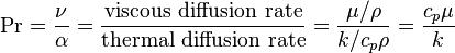
: momentum diffusivity (kinematic viscosity), \nu = \mu/\rho, (SI units: m2/s)
  • \alpha : thermal diffusivity, \alpha = k/(\rho c_p), (SI units: m2/s)
  • \mu : dynamic viscosity, (SI units: Pa s = N s/m2)
  • k : thermal conductivity, (SI units: W/m-K)
  • c_p : specific heat, (SI units: J/kg-K)
  • \rho : density, (SI units: kg/m3)


Small values of the Prandtl number, Pr << 1, means the thermal diffusivity dominates. Whereas with large values, Pr >> 1, the momentum diffusivity dominates the behavior. For example, for liquid mercury the heat conduction is more significant compared to convection, so thermal diffusivity is dominant. However, for engine oil, convection is very effective in transferring energy from an area in comparison to pure conduction, so momentum diffusivity is dominant.

In heat transfer problems, the Prandtl number controls the relative thickness of the momentum and thermal boundary layers. When Pr is small, it means that the heat diffuses quickly compared to the velocity (momentum). This means that for liquid metals the thickness of the thermal boundary layer is much bigger than the velocity boundary layer.


Reynold’s Number

As an object moves through the atmosphere, the gas molecules of the atmosphere near the object are disturbed and move around the object. Aerodynamic forces are generated between the gas and the object. The magnitude of these forces depend on the shape of the object, the speed of the object, the mass of the gas going by the object and on two other important properties of the gas; the viscosity, or stickiness, of the gas and the compressibility, or springiness, of the gas. To properly model these effects, aerodynamicists use similarity parameters which are ratios of these effects to other forces present in the problem. If two experiments have the same values for the similarity parameters, then the relative importance of the forces are being correctly modelled.

Aerodynamic forces depend in a complex way on the viscosity of the gas. As an object moves through a gas, the gas molecules stick to the surface. This creates a layer of air near the surface, called a boundary layer, which, in effect, changes the shape of the object. The flow of gas reacts to the edge of the boundary layer as if it was the physical surface of the object. To make things more confusing, the boundary layer may separate from the body and create an effective shape much different from the physical shape. And to make it even more confusing, the flow conditions in and near the boundary layer are often unsteady (changing in time). The boundary layer is very important in determining the drag of an object. To determine and predict these conditions, aerodynamicists rely on wind tunnel testing and very sophisticated computer analysis.

The important similarity parameter for viscosity is the Reynolds number. The Reynolds number expresses the ratio of inertial (resistant to change or motion) forces to viscous (heavy and gluey) forces. From a detailed analysis of the momentum conservation equation, the inertial forces are characterized by the product of the density rho times the velocity V times the gradient of the velocity dV/dx. The viscous forces are characterized by the dynamic viscosity coefficient mu times the second gradient of the velocity d^2V/dx^2. The Reynolds number Re then becomes:

Re = (rho * V * dV/dx) / (mu * d^2V/dx^2)

The gradient of the velocity is proportional to the velocity divided by a length scale L. Similarly, the second derivative of the velocity is proportional to the velocity divided by the square of the length scale. Then:

Re = (rho * V * V/L) / (mu * V / L^2)

Re = (rho * V * L) / mu

The Reynolds number is a dimensionless number.

The Reynolds number can be further simplified if we use the kinematic viscosity nu that is equal to the dynamic viscosity divided by the density:

nu = mu / rho

Re = V * L / nu

Reynolds Number is used to determine whether a flow will be laminar or turbulent. If Re is high (>2100), inertial forces dominate viscous forces and the flow is turbulent; if Re is low (<1100), viscous forces dominate and the flow is laminar.

Immersion Cooling Emerges as New Cooling Technology

Immersion cooling, in which electronics are submerged in liquid coolants, is gaining popularity in the cooling industry. Companies have become aware of the benefits of immersion cooling in extreme environments, such as oil rigs or in the desert. The U.S. military is also considering liquid-immersion cooling to save energy in tropical camps.

Two types of liquid-immersion cooling include single-phase and two-phase. Single-phase is when an electronic device is placed in a metal case, and the liquid absorbs heat from the electronic device as the liquid flows over the case. The liquid is then pumped to a cooling unit outside, thus reducing the temperature.

Two-phase is a more complex process. “Heat from electronic components vaporizes liquid coolant, which condenses again in an outside unit as the heat is transferred to water. A fluid called Novec made by 3M is popular because it changes easily between gas and liquid and doesn’t adhere to electronics,” according to researchers.

Liquid immersion cooling has proved more successful than other cooling methods, since air cooling and other methods still require fans or air conditioners. Immersion cooling also saves 20 percent on costs, 40 percent on power and 60 percent on space.

“Liquid cooling will grow at about 16 per cent per year through 2019. The military is expected to drive modular designs because it operates in remote locations and requires security and mobility,” according to TechNavio.

Some companies that have already begun using immersion cooling include Icetope, LiquidCool Solutions (LCS), and Allied Control and Silicon Graphics Inc. (SGI). Icetope and LCS use single-phase cooling and SGI uses two-phase cooling.